Test cases
-
CI1 - Inviscid bow shock
The detached bow shock upstream of a 2D simple blunt body in inviscid conditions is studied. This case is designed to isolate testing of the shock-capturing properties of schemes. This case is computationally expedient, being steady, two-dimensional, inviscid flow, with well-defined boundary conditions.
The geometry is a flat center section, with two constant radius sections top and bottom. While the flow is symmetric top and bottom, a full domain is computed to support potentially spurious behavior. The aft section of the body is not included to avoid developing an unsteady wake. Two sets of structured meshes are provided. For finite volume type codes, straightsided meshes in CGNS are provided, whereas for finite element like methods, a series in gmsh format is provided, derefined as a function of the order of accuracy N. Participants can additionally provide results on unstructured meshes.
The assessment criteria include the conservation of total enthalpy as well as the comparison of stagnation pressure with respect to theory.
Please follow the presentation guidlines when creating your presentation.
NOTE: There is an indexing error in the Q4 gmsh grids. Scott Murman will fix this if someone requests it to be fixed.
Update June 7 2017: Added clarification for normalization of error calculations.
-
CI2 – Inviscid Strong Vortex-Shock Wave Interaction
This case is designed to verify that a scheme can capture complex physical phenomena resulting from the interaction between a strong vortex and a shock wave. This is a two-dimensional unsteady inviscid flow including multiple shock discontinuities. When the strong vortex and the strong shock wave encounter, considerable distortion of shock structure occurs, followed by the generation of linear and non-linear waves propagating onto the downstream flow fields. Two distinctive physical phenomena can be observed in this problem. First, the strong vortex is split into two separate vortical structure due to the compression effects of the shock passage. The post-shock vortical structure depends strongly on the relative strength of the shock and the vortex. Second, cylindrical acoustic wave structure appears on the downstream side of the stationary shock. The sound waves centered on the moving vortex core are partly cut off by the shock wave. As a result, alternating expansion and compression regions are observed.
Andrei Cimpoeru has generously provided a python script that can be used to generate the intial conition for this test case.
Please follow the presentation guidlines when creating your presentation.
UPDATE: July 5 2017: Expression for initial condition rather than a rounded number.
Meshing information:
In the cases of CGNS format, grid files (.cgns) are provided directly. Participants can use them without any pre-processing.
In the cases of GMSH format, GMSH script files (.geo) are provided. Participants can generate each type of meshes by using the GMSH script files and the GMSH program.
In the cases of both "M" and "IT" type meshes, follow the instuctions provided in each GMSH script file to apply a certain meshing algorithm (i.e. Delaunay).
In GMSH script files, participants can modify the variable "nx" to change the grid size.
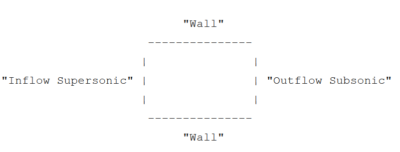
For example, if you want to generate "RQ100" mesh, insert "100" into "nx" in the "RQ.geo" file.Physical boundary conditions are set as follows:
. GMSH-type grids:
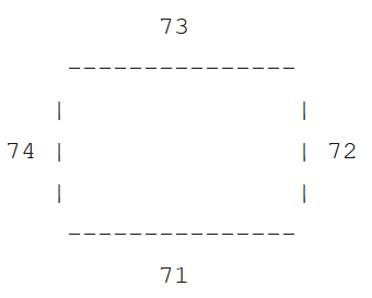
. CGNS-type grids:
-
CL1 - Heaving and pitching airfoil
This problem is aimed at testing the accuracy and performance of high-order flow solvers for problems with deforming domains. A NACA 0012 airfoil is undergoing a smooth flapping-type motion, starting from rest at zero angle of attack and ending at a position one chord length higher. The metrics used to assess the accuracy of the solution are the total energy (i.e. integrated power) extracted from the flow during the motion and the vertical impulse imparted on the airfoil by the flow (integrated vertical force). The viscosity is constant and the Reynolds number with respect to the chord length is Re=1000.
Please follow the presentation guidlines when creating your presentation.
-
CR1 - Common Research Model
The common research model (CRM) was extensively studied with state-of-the-art CFD codes in the sixth drag prediction workshop (DPW-6). The objective of this test case is to obtain mesh-converged lift, drag and moment coefficient values on the CRM wing-body configuration at cruise conditions. This test case is primarily intended to assess hp-adaptation schemes, but fixed grid results are also welcome. A series of curved finite element methods are provided, and a large number of grids on the DPW-6 website available with various grid topologies. In addition, Steve Karman of Pointwise has provided a set of curved meshes here in CGNS and gmsh file formats. As the CGNS standard is vague on the reference coordinate location of face coordinates of quartic (P4) tetrahedral elements, the CGNS files provided by pointwise uses equidistributed nodes on the reference element.
Please follow the presentation guidelines when creating your presentation.
-
CS1 - Tandem Spheres Re=3900
The aim of this test case is to asses the accuracy and efficiency of high-order solvers for the prediction of complex unsteady multi-scale flow under low Mach and low Reynolds number conditions. A uniform free stream initial condition is specified from the Mach number (M = 0.1), Reynolds number based on single sphere diameter, D, (Re = 3900), and Prandtl number (P r = 0.72). To enable a manageable work load through spatial and temporal resolution studies the comparison of quantities of interest is to be carried out on the non-dimensional time interval t ∈ [100, 200].
All hexahedral and all tetrahedral girds provided by Steve Karman of Pointwise and Samuel James of GridPro are available here in CGNS and gmsh file formats. As the CGNS standard is vague on the reference coordinate location of face coordinates of quartic (P4) tetrahedral elements, the CGNS files provided by pointwise uses equidistributed nodes on the reference element.
NOTE: As of 6/10/2017 the writeup for this test case has changed the verification test from the laminar Joukowski airfoil to the Taylor Green Vortex.
Please follow the presentation guidelines when creating your presentation.
-
CS2 - T106 LPT Cascades
This test case concerns the spanwise periodic DNS or LES of the transitional and separated flow on the T106A and T106C subsonic turbine cascades. These are well-known test cases for assessing transition models for low Reynolds numbers. The first test case concerns the T106A at Re=60.000, while the T106C is computed at Re=80.000. As the inlet turbulence is very low, both flows feature laminar separation and transition in the reattachment zone or in the wake.
Although mesh configurations are fully free, cascade CAD files (igs, stp) as well as curved meshes (unstructured and extruded triangular/quadrilateral) can be provided on request.
-
MC1 - High-Lift Common Research Model
The high-lift CRM configuration has been jointly designed by NASA and Boeing to serve as a test case for high-lift simulation. The geometry is representative for a wide-body commercial aircraft with a classical three element high lift system at the wing leading and trailing edge in a landing setting. This version of the geometry, which consists of a body, wing, and three flaps, but no attachment hardware, was introduced for the Third High Lift Prediction Workshop (HiLPW3) https://hiliftpw.larc.nasa.gov/ and the accompanying first Geometry and Mesh Generation Workshop http://www.pointwise.com/gmgw/.
Issues with the original CAD files used at the two workshops have been resolved in the CAD file provided here. Please use step file provided here for generating meshes.
As the CGNS standard is vague on the reference coordinate location of face coordinates of quartic (P4) tetrahedral elements, the CGNS files provided by Pointwise uses equidistributed nodes on the reference element.
-
MC2 - NASA Rotor 67
The NASA rotor 67 is a well-known validation test case for turbomachinery CFD codes. The aim of this challenge is to see whether fully unstructured high order simulations can be performed.
A first type of contribution concerns the generation of the curved (hybrid) unstructured meshes for a single passage. The requirements are
- minimally quadratic interpolation of the geometry;
- local mesh refinement following size control maps in leakage flow regions;
- curved rotationally periodic boundaries;
- extrusion curved boundary layer meshes, with an aspect ratio up to 1000 for RANS.
For meshing purposes the CAD of a single passage with and without tip gap is available in parasolid and step format. The full rotor has 22 blades.
The second type of contribution concerns the actual RANS/LES/WMLES computation at two operating points, ie. near the design point and near stall. The computation will at least be taken up by the test case leader. For computational contributions, block structured curved meshes will be provided on request.
-
VI1 Vortex transport by uniform flow
This problem is aimed at testing a high-order method’s capability to preserve vorticity in an unsteady inviscid flow. Accurate transport of vortexes at all speeds (including Mach << 1) is very important for Large-Eddy and Detached-Eddy simulations, possibly the workhorse of future industrial CFD simulations, as well as for aeronautics/rotorcraft applications. This verification case is particularly suitable for verifying temporal order of accuracy.
-
VI2 Smooth Gaussian bump
This problem is aimed at testing high-order methods for the computation of internal flow with a high-order curved boundary representation. In this subsonic flow problem, the geometry is smooth, and so is the flow. Entropy should be a constant in the flow field. The L2 norm of the entropy error is then used as the indicator of solution accuracy since the analytical solution is unknown. The convergence rate can be expected to be P+1, where P is order of the discrete polynomial approximation.
The set of structured quad or triangle grids are generated by the python scripts provided on the web site. The type of meshes, the interpolation order and the number of refinements are specified through options specified at the end of the Smoothbump.py script.
-
VL1 Laminar Joukowski airfoil at Re=1000
This test case concerns the laminar flow around a symmetric Joukowski airfoil at zero incidence. It is designed as a verification case of the viscous terms of the Navier-Stokes equations. A low Reynolds number of 1,000 is employed to emphasise the viscous terms. For an adjoint consistent discretization, the optimal convergence rate for an output functional is 2P. Otherwise, the convergence rate can be expected to be P+1. The Joukowski airfoil is used for this test as the cusped trailing edge removes the inviscid singularity at the trailing edge. However, there is still a singularity in skin friction. The provided grids are design to cluster nodes at both the trailing edge singularity and the stagnation point in order to capture the expected order of accuracy. Hence, all participants must use the provided grids.
-
VR1 RANS Joukowski airfoil
This test case is designed as a verification case of the turbulence model of the RANS equations. Participants are required to use the provided grids, as they have been demonstrated to be able to provide the optimal convergence rate in drag. A Reynolds number of 1,000,000 is employed. For an adjoint consistent discretization, the optimal convergence rate of an output functional is 2P. Otherwise, the convergence rate can be expected to be P+1. The Joukowski airfoil is used for this test as the cusped trailing edge removes the inviscid singularity at the trailing edge. However, there is still a singularity in skin friction. The provided grids are design to cluster nodes at both the trailing edge singularity and the stagnation point in order to capture the expected order of accuracy. Hence, all participants must use the provided grids.
-
WS1 DNS of the Taylor-Green vortex at Re=1600
This problem is aimed at testing the accuracy and the performance of high-order methods on the direct numerical simulation of a three-dimensional periodic and transitional flow defined by a simple initial condition: the Taylor-Green vortex. The computational domain is a triply periodic cubic domain, in which initially 8 vortices reside, described by an analytical formula. This flow transitions to turbulence, with the creation of small scales, followed by a decay phase similar to decaying homogeneous turbulence.
Participants are expected to perform a grid independence study on Cartesian meshes, as well as a few computations on unstructured/perturbed meshes at similar resolution as the Cartesian ones. The assessment criteria consist of the evolution of the energy dissipation rate as well as the enstrophy. Further verification is done on the basis of the kinetic energy spectrum as well as the trace of the vorticity on the periodic plane at selected time steps.
Computations need to be run on Cartesian meshes with specified equivalent resolutions 64, 128 and 256. If applicable, it is expected that participants use the unstructured and perturbed meshes provided by the test case leader to guarantee a level playing field. These will be generated in function of the interpolation (order) used by the discretization.
-
WS2 LES of the plane channel at Ret=550
This test case concerns the LES of the channel flow at Reτ=550. This well-known benchmark has been intensively studied by the turbulence community. DNS and LES of the flow have been performed by numerous authors. Therefore, various quantities are available to assess the accuracy of the LES approach, such as averaged velocity and velocity fluctuations profiles and kinetic energy spectra.
Participants are expected to perform the computations for a set of structured grids which will be provided on request. Additional computations on unstructured meshes are also welcome. The assessment criteria include spatially and temporally averaged wall normal variations of the velocity and its correlations.
The participants are expected to use the meshes - structured, unstructed, and 2D extruded - provided by the test case leader in order to ensure similar grid spacing near the wall for all participants. These will be generated/provided on request as a function of the interpolation used by the discretisation method.
NOTE: This test case is slightly different from the previous edition.